Fast PWM on an ATmega32U4 (Arduino)
On my path to a peltier temperature controller, I stumbled upon the requirement to generate fast PWM signals using a MCU. Some pointers to good introductions, as well pages in the datasheet and sample code for ATmega32U4 (Arduino Leonardo) which I had laying around for tests.
Motivation
The normal ATMega PWM frequency is about 500 Hz and too low for this application, having a far too big ripple effect on current and voltage. TEC elements should be driven in the kHz range or even better with constant current, see the TI Application Report under the links section for more information.
Prerequisites
- Board: Arduino Leonardo R3
- MCU: ATmega32U4
- IDE: VSCode / PlatformIO
Links
- Datasheet: Atmel-7766-8-bit-AVR-ATmega16U4-32U4_Datasheet.pdf
- Good explaination on timer control registers and modes on YouTube: Jonathan Currie - megaAVR Microcontrollers: Fast PWM Generation
- Another implementation: [Project] Temperature Control of Peltier Element
- Texas Instruments Application Report - Driving a Peltier Element (TEC): Efficiency and Aging
Demo Code
We are using Mode 7 for fast PWM waveform generation and setting the counter to a 10-bit resolution, with clear on compare match counter mode.
The following code is just an example and used for this demo. pwmVal is initally set close to max (1024), for demo purposes. Explainations and corresponding datasheet page numbers in the code comments.
File: main.c
#include <Arduino.h>

// Leonardo ATMEGA32U4:
// 13.6.3 Fast PWM Mode, Page 100

uint16_t pwmVal = 1000;
char serialMsgBuf[32];

void setup() {
  Serial.begin(9600);

  // Clear Timer/Counter Control Register A & B
  TCCR1A = 0;
  TCCR1B = 0;

  // Table 14-4. Waveform Generation Mode Bit Description. Page 133
  // Mode:7 - 0 1 1 1 - Fast PWM, 10-bit 0x03FF TOP TOP
  TCCR1A |= (1 << WGM11) | (1 << WGM10);
  TCCR1B |= (0 << WGM13) | (1 << WGM12);

  // Table 14-5. Clock Select Bit Description. Page 134
  // 0 0 1 ..   /1 = 15.62 kHz PWM
  // 0 1 0 ..   /8 =  1.95 kHz
  // 0 1 1 ..  /64 =    244 Hz
  // 1 0 0 .. /256 =    61 Hz
  TCCR1B |= (0 << CS12) | (0 << CS11) | (1 << CS10); // 0 0 1 ... clkIO/1 (No prescaling)

  // Table 15-7. Compare Output Mode, Phase and Frequency Correct PWM Mode. Page 165
  // COM4A1..0 = 0b10
  //   Cleared on Compare Match when up-counting.
  //   Set on Compare Match when down-counting.
  TCCR1A |= (1 << COM1A1) | (0 << COM1A0);

  // Define Arduino PIN 9 as output. Page 75
  // (PCINT5/OC1A/#OC4B/ADC12) PB5 --> Port B Bit 5 --> Package Pin 29 --> Arduino Pin 9
  /*
    OC.4B: Timer 4 Output Compare B. This pin can be used to generate a high-speed PWM signal from Timer 4
    module, complementary to OC.4B (PB5) signal. The pin has to be configured as an output (DDB5 set (one)) to
    serve this function.
  */
  DDRB |= (1 << DDB5);
}

void loop() {
  pwmVal += 25;
  OCR1A = pwmVal % 1025;

  sprintf(serialMsgBuf, "PWM: %i, mod(1025): %i", pwmVal, pwmVal % 1025);
  Serial.println(serialMsgBuf);

  delay(500);
}
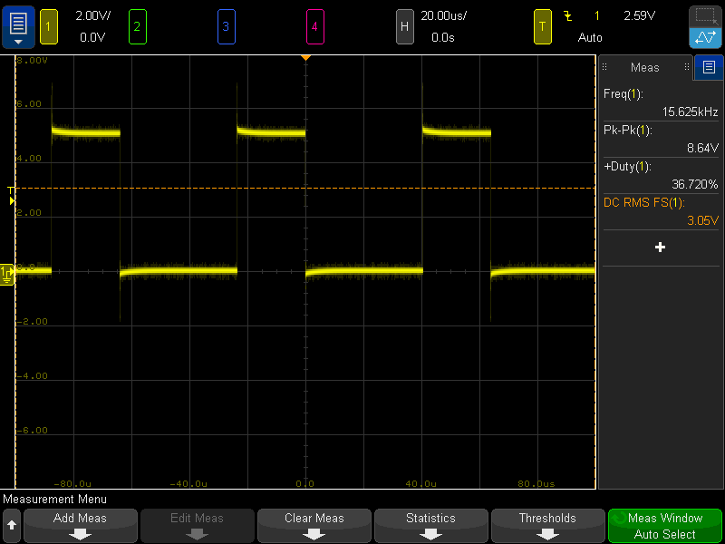
Verifying the fast-pwm with the oscilloscope:
PlatformIO Configuration
VSCode PlatformIO configuration:
File: platformio.ini
[env:arduino]
platform = atmelavr
board = leonardo
framework = arduino
